 Projects
 Hydrodynamic Studies
| Camera Locations | |
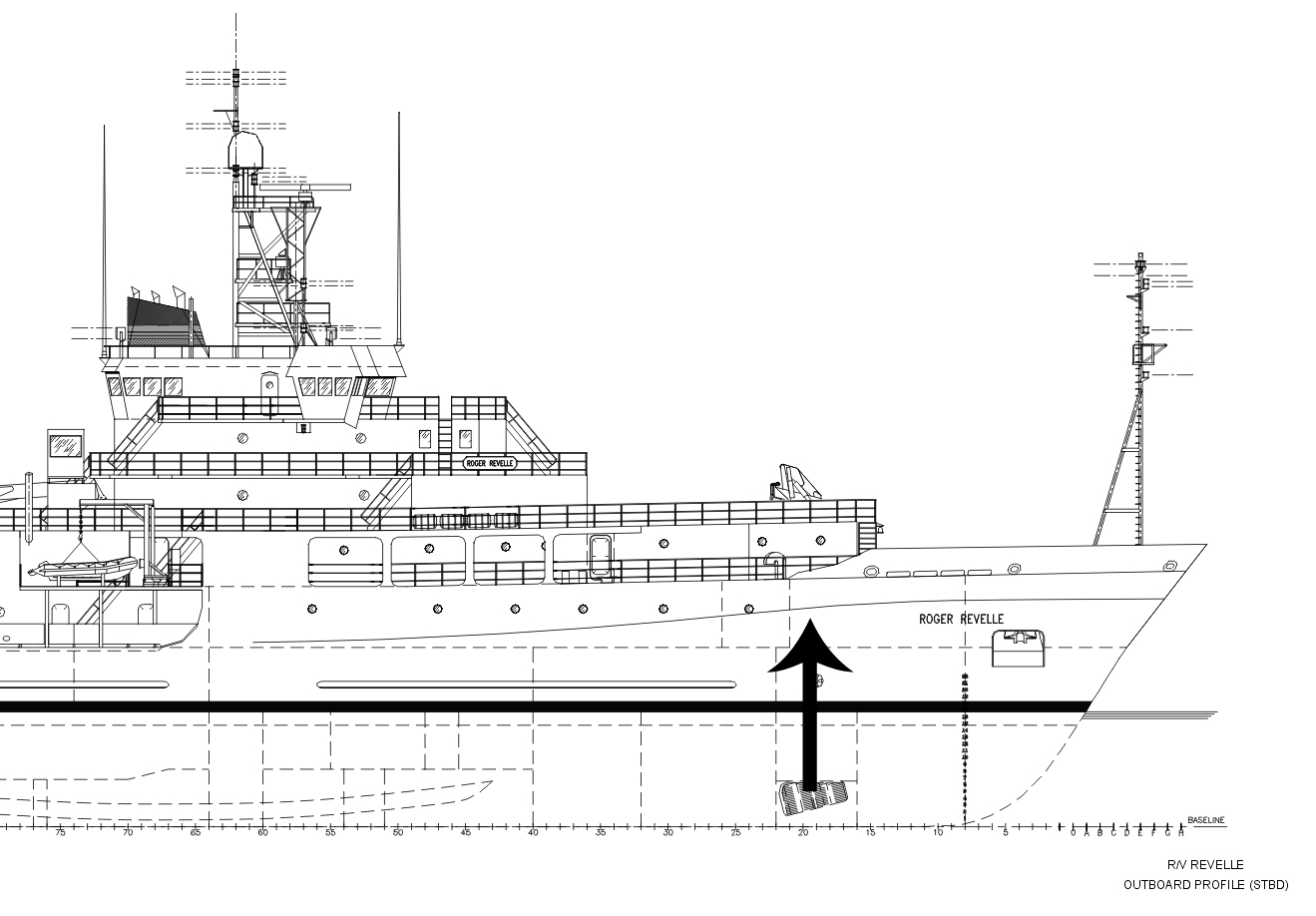
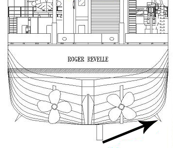
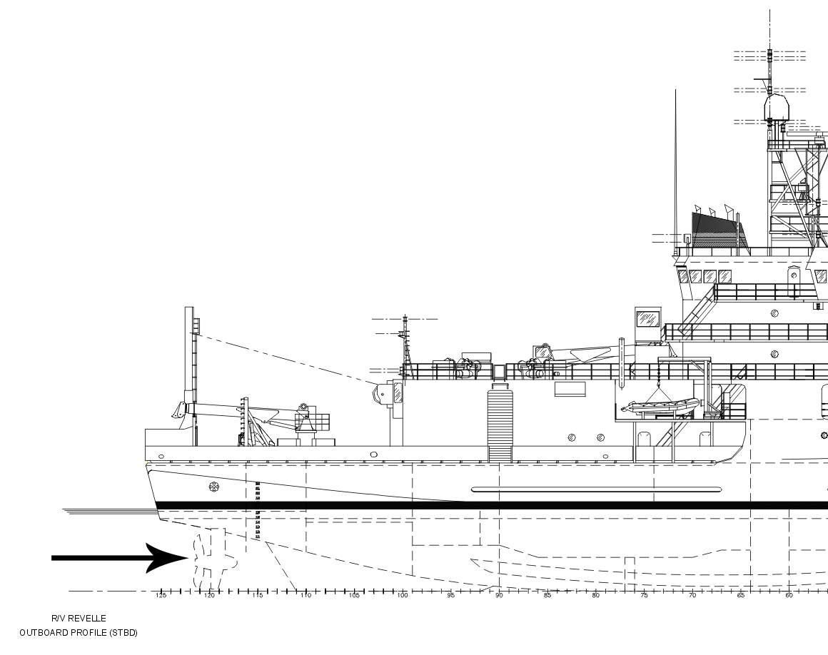
| *The arrow in the following images indicates the view of the ship from the respective camera. | |
|
|
| Bowcam View | Pipestring View |
|
|
| Sterncam View | |
| Bowcam: | |
| The Bowcam was attached with hooks (see Fig.1) to the grate (see Fig.2 & Fig.3) on the starboard side of the ship (see Fig.4). | |

Fig.1 Bowcam and Camera Mount
|

|

Fig.3 Grate
|

Fig.4 Camera Location
|
| Pipestring: | |
| The pipestring was inserted into the transducer tube depicted in Fig.5 and Fig.6. Pictures of the tube are shown in Fig.7-Fig.10. What the camera was pointed at is shown in Fig.11. | |
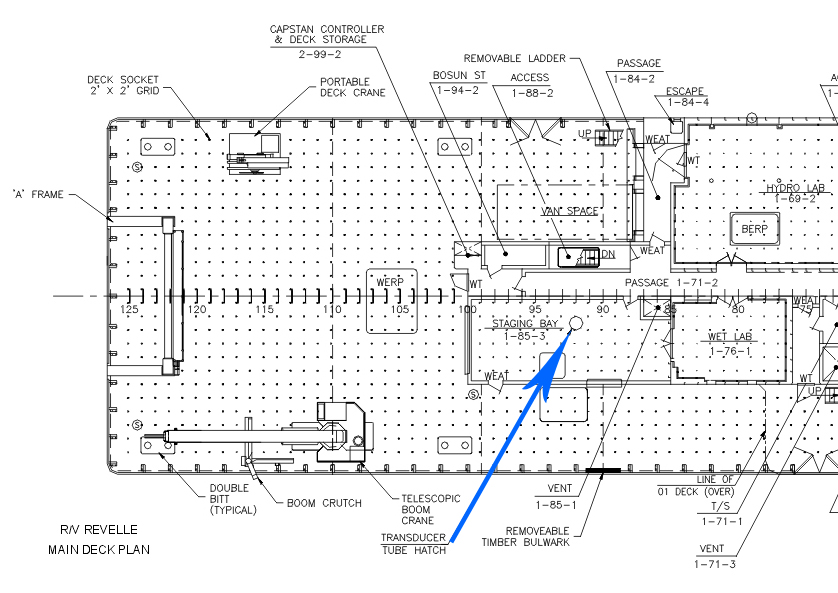
Fig.5
Top Side View of Transducer Tube Location
|
|
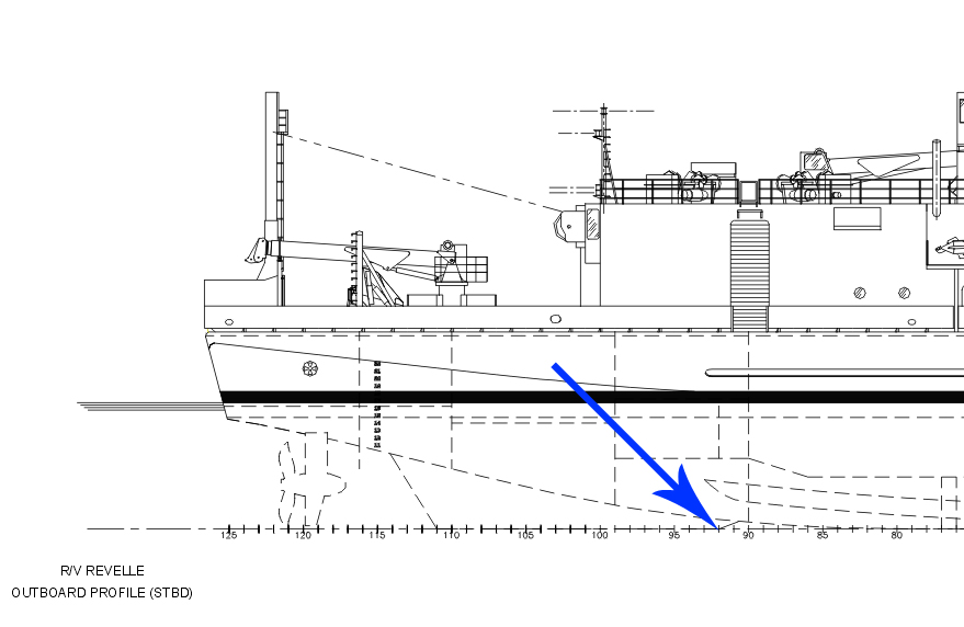
Fig.6
Bottom Side View of Transducer Tube Location
|
|

Fig.7 Transducer Opening Top Side
|

Fig.8 Transducer Opening Bottom Side
|

Fig.9 Braking Mechanism
|

Fig.10 Pipestring in Transducer Tube
|
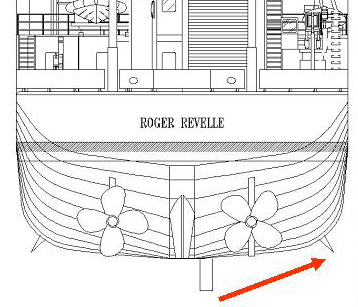
Fig.11 View from Stern |
|
|
Image sequence (fig.12-Fig.17) from imagery taken beneath the R/V Revelle while it was underway
at approximately 14kts. Video was shot using an underwater pan/tilt unit deployed
in a moonpool approximately 20m forward of the stern. This sequence of images
looking into the flow shows the variability in bubbles present beneath the vessel's
hull. Fig.12-Fig.13 shows the varying bubble density. Looking aft (fig.15 & Fig.16, the bubbles beneath the hull) are seen to be swept into the vessels propulsors. Fig. 17, looking to the side perpendicular to the flow, filaments of high-density bubble collections are observed to be swept into the bulk flow of the vessel's wake. Moonpool imagery provided by the Ocean Physics Group, Scripps Institution of Oceanography. |
|

|

|

|

|

|

|
| Sterncam: | |
Fig.18 is of the bubble measurement system that the sterncam was attached to. The system was
designed for deployment at the stern of the Revelle and was attached to the traversing stern
mount (Fig.19). The various components of the measurement system include:
The sensor system was operated at speeds up 14 knots at various locations across the beam of the Revelle. The angle of the camera was tilted to look at the propeller or the transom. Also, the stern mount allows for the position of the camera to be adjusted horizontally along the stern (see Fig.20 & Fig.21). |
|

fig.18 Sterncam
|

fig.19 Stern Mount
|

fig.20 Camera Position 1
|

fig.21 Camera Position 2
|
| -top- | |